Pulley system analysis
Tuomas Pöysti, a good friend of RopeLab, has written this article presenting his thoughts on analysing pulley systems.
Foreword
I am more interested in pulley systems than they deserve as practical tools. If you read this and don’t understand what this is good for, you should stop reading and do something that is more useful to you. If there is just a single person other than me on the planet who finds this text intellectually stimulating, my work was worthwhile.
An expert reader might notice that the literature study behind this work is inadequate. I cannot say I have carried out proper searches on scientific databases, and I have read just a couple of text books that have even a chapter about pulley systems. For a non-expert reader it is even more important to understand that this work is not based on solid, peer-reviewed body of earlier publications, as the case should be if we wanted this to be really scientific. Please do not let the fancy words mislead you. And talking about words, at least some of the terminology used here probably differs from the established one, which I simply am unaware of. I’m very thankful for all suggestions.
Hopefully my obviously non-native English won’t further complicate understanding this. The ideas presented here are actually not very difficult, and I tend to pursue unambiguous expression and avoid unjustified jargon. I admit, though, that I could have succeeded even better. Please ask me if you try to get it, want to get it but cannot get it. Finally, I salute to all of you who have the persistence to go through the whole thing.
Scope and definitions
Pulleys are rope rigging devices that ideally have the capability of deviating a rope without affecting the tension of the rope, i.e. so that the rope inevitably has equal tension on each side of the device. Real life pulleys are not ideal, of course, but this can be to some degree managed by applying an efficiency value. Figure 1 shows a (schematic) pulley, which has efficiency P (0 < P < 1). When the rope is tensioned on the right side by force F, friction inside the pulley and the rope (and possibly between them) lets only force P*F through the pulley to the left side. In real life, using nylon ropes and pulleys of reasonable size, efficiency (P) is typically around 0.8.

Note that the markings in figure 1 are not vectors, but the arrow indicates the direction of rope movement or location of tensioning. This is important, since it obviously dictates which side has greater tension. The forces are scalar and their directions have to be interpreted from the schematics. In this case, because the pulley is in rest, the downward force applied to it must equal F + P*F. This setup is also a simple pulley system, usually referred to as a “V” or “V-rig”.
Pulley systems in general are any combinations of pulleys and rope like elements. Another minimum requirement for pulley systems could be that they have a single degree of freedom, implying that positions of all of the elements are unambiguously related to each other, especially to the position of a certain element, which is here called the input element. (See later note on resetting.) The input element is the one through which the force/energy is applied to the system.
Another special element of a pulley system is the output element, to which the load is connected. The purpose of pulley systems is to have a larger force at the output element (Fo) than at the input element (Fi). The relationship Fo/Fi is called the mechanical advantage, MA.
Ideal MA is based on the assumption that all pulley efficiencies equal 1, such that each pulley effectively doubles a force. In this paper, the term “ideal” is often skipped for brevity. Any real life MA may be referred to as “effective MA”. It can be either measured by attaching load cells to the input and output elements, or calculated. The term “calculated MA” is particularly used in the latter case. Ideal MA of above shown V is 2:1, and calculated MA could be for example F+PF, as stated, or 1+P if represented as force multiplier coefficient. The ratio effective MA / ideal MA is the efficiency of the pulley system. The picture below illustrates a simple (ideally) 3:1, also known as Z-rig. The pulleys are labelled P1 and P2. On the right it is divided into elements. There are multiple useful ways of doing this, and in this case the criterion has been separating individually moving parts of the system.

Ideally all rope elements of a pulley system are collinear, though for practical reasons this is not the case in reality and even less in the schematic pictures. That is, when the input element is pulled, each element moves either upwards or downwards. In this paper, elements moving upwards are said to have positive direction and the ones moving downwards have negative direction. The stationary element G (ground) is neutral in this sense. If input and output elements have different directions, the pulley system is direction changing.
Also pulleys are in this paper labelled as positive or negative based on their orientation. P1 has negative direction and P2 positive direction. See figure 3.

In this paper, only pulley systems that yield to force analysis, are of concern. Typically this means, in addition to the requirement about single degree of freedom, that the force path branches inside the pulley system in a certain way. To keep this paper at least relatively simple, formal definition is skipped.
As a final note on the scope: for most of this paper, the issue of resetting does not make any difference. We are not interested in stroke distance or collapse rate or any such real life things. Pulley P2 in figure 2 could as well be attached to element E1 by a rope clamp or a knot, since only a small imaginary pull is needed for the sake of the analysis.
Force analysis
Figure 4 illustrates a pulley system which I have called “5:1 crevasse”, although I have lost the source for this name and now it really does not seem that common. Anyway, this three pulley, ideally 5:1 pulley system is analysed by assuming force F on the input element and then working towards the output element, calculating the resulting forces on each element. For simplicity, letter F is replaced by 1, and thus all resulting terms are multipliers of force F. Sometimes letter T (for tension) is used, and the whole method might be called T-method, but this is just a difference in notation.
Every time a rope runs through a pulley, the force before the pulley must be multiplied by the pulley’s efficiency. In this case, the elements that are segments of the grey rope, are thus tensioned by forces 1, P2 or P1P2 (*F). Every time two elements work to pull one element, the force on the latter is the sum of the forces of the two elements. For example, 1+P2. Another point of forces summing up is what David Fasulo calles “tractor” in his book, the point where P3 is attached to the element that comes down from P1. Here 1+P2, P3+P2P3 and P1P2 are summed as the calculated MA of the pulley system.

Let’s study the result. First of all, the output force consist of five terms. Considering that 0 < Px < 1 for each P1, P2 and P3, each term (with exception of “1”) has the same range 0…1. That is,
- the maximum value of the sum is 5 (P1=P2=P3=1) and
- the maximum contribution of each term is 1.
What do these terms stand for, then? Starting with the first term “1”, it will only manifest for pulley systems which do not change the pull direction, i.e. pulley systems in which the input and output element move in same direction. And it makes sense if one imagines all pulleys being extremely bad, so bad that the result is rigid connection between three strands of rope. This is what pulley efficiency 0 would be like. Even in this extreme case, pulley systems that have term “1” in their calculated MA equation, have MA of 1. As does a straight rope.
Continuing this mind experiment, let’s rigidify each pulley one by one. We find out that each term has a corresponding sub pulley system, a possible path of energy through the system.
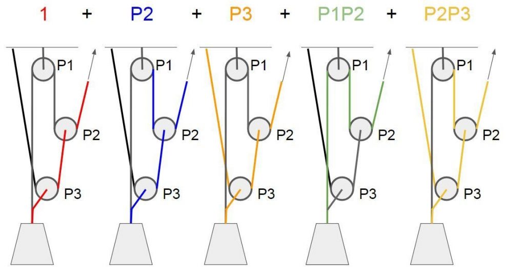
The red path related to term “1” was already explained. P2 resembles a V rig (2:1) and so does P3. P1P2 is for a Z-rig and P2P3 a 4:1 “V on V”.
About the terms
What other terms could there be? P1 is an obvious candidate. Again going back to the mind experiment, if we lock pulleys P2 and P3, we gain no benefit by letting P1 roll, so it does not make any difference to the system. Further, term P1 should be related to a path which flows through pulley P1 solely. Otherwise efficiencies P2 or P3 would also be present in the term. And how could it even be possible for a negative direction pulley such as P1 to be the only pulley through which the energy flows on a path, while pulleys are the only means of changing direction of force? I’m not going to prove this any more formally right now:
Pulleys with negative direction never appear alone as a term in a calculated MA, if the pulley system is not direction changing. More generally, pulleys with different direction than the input element won’t.
Let’s do the same for a couple of other pulley systems. Figure 6 illustrates a 9:1 “Z on Z” and a variation of it, a 11:1. Neither changes pull direction, so each should have “1” as a term. Further, they should have 9 and 11 terms, respectively, and terms P1 and P3 should be absent.

The analysis yields calculated MA’s: For 9:1
1 + P2 + P4 + P1P2 + P2P4 + P3P4 + P1P2P4 + P2P3P4 + P1P2P3P4
And for 11:1
1 + P2 + P4 + P1P2 + P1P4 + P2P4 + P3P4 + P1P2P4 + P1P3P4 + P2P3P4 + P1P2P3P4
Besides the fourth pulley, there is something new here. The term P1P2P3P4 means now there’s a path through all the pulleys, which was absent in the 5:1 case. There are terms of different degrees present from 0 (term “1”) to 4 (P1P2P3P4).
Could a term manifest multiple times? I claim that it is impossible, although I again am not able to give a solid and formal proof. But it would mean that two independent energy paths flow through exact same sequence of pulleys.
How about power terms like P1P1 or P2P2P2, or in general a pulley manifesting itself in a term several times? Again, not formal nor solid, but it would require a loop where an energy path passes same pulley twice. Only one rope runs through each pulley.
So, to be proven later and by more intelligent people, we take as a premise:
Each term, a product of combination of pulley efficiencies, appears at maximum once in a calculated MA (1). Further, each pulley’s efficiency may appear at maximum once in each term (2).
It follows that using N pulleys, the maximum number of pulley efficiencies in a single term is N. A term is a product of maximum N efficiency values, thus the maximum degree of a term is N. The other degrees between (possible) zeroth degree term and the Nth degree term are combinations of pulleys, like “P1P3P4” etc. The possible terms up to fourth degree are:
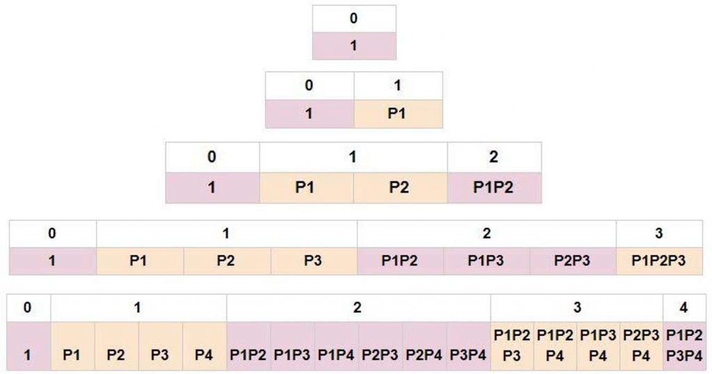
Luckily this is familiar looking structure. Mathematicians have known this for centuries, although a white man called Pascal has later taken most of the credit, this is known as Pascal’s triangle. It resembles array of binomial coefficients for different degrees. No need to be intimidated, this just means (among other things) that we know the number of terms on each row, no matter how far we go downwards. The number of terms on row N is 2N (the top row being zeroth).
So if the premises above hold, the maximum number of terms in the calculated MA, and thus the maximum ideal MA of a pulley built using N pulleys is 2N. Row one: What is a pulley system having zero pulleys? A rope, which obviously has MA 1. Row two: Using one pulley, there seems to be two possible pulley systems, V and V upside down. The ideal MA of the former one is 2 and the latter one 1, it being just a pull direction changer. Their calculated MA’s would be 1+P1 and P1, respectively. As stated earlier, in the case of upside down V, there could not be a first order term P1, since the pulley is in negative direction.

How about the third row, pulley systems having two pulleys? At least we have the famous Z-rig or simple 3:1 (1+P1+P1P2, see figure 2) and ideally 4:1 “V on V” or “piggyback”, see figure 8. The latter can also be turned upside down to achieve an ideally 3:1 direction changing system. This system does not have term “1” because it is direction changing, but for the same reason it has both terms P1 and P2 even though the corresponding pulleys’ directions are negative.

It seems that “V” and “V on V” do a good job getting all possible terms. Actually all the clues lead into this direction, if you think about it. The maximum ideal MA for N pulleys, 2N, means that each added pulley needs to double the MA. All pulleys should have the same direction as the input element (to get all first degree terms). Again, I’m not going to formally prove this, but there most probably are not other solutions to this than “V on V on V on …. On V”. At least there is a pulley system that has MA of 2N, no matter how many N pulleys is used to build it.
Let’s study some three pulley systems and how they fill in the boxes:
- Crevasse 5:1, see figure 4
- Simple 4:1, see figure 9
- 7:1 (double) mariner, see figure 9
- V on Z and vice versa, see figure 9
- V on V on V and same upside down, see figure 9
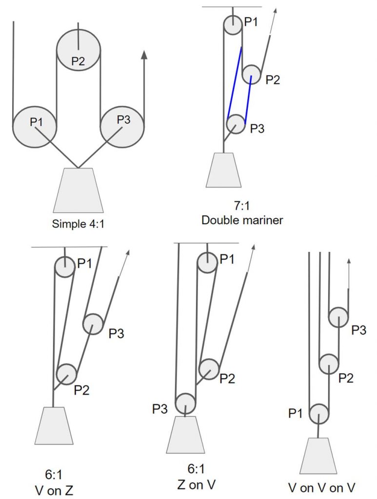
These pulley systems have the following terms in their calculated MA’s:

Some notes on this. The cases “V on Z” and “Z on V” quite nicely show that there may be several different pulley systems that have identical calculated MA expression. This also more or less shows the tendency of the pulleys closer to the input element to appear more frequently in the terms. The numbering of the pulleys is of course completely dependent on definition, but I like to label the most obvious one to act as progress capture device (PCD) as P1, and it is usually not close to the input element. As can be seen here, terms P2 and P3 tend to be more frequent ones.
Pulley system efficiency
Where do we want the ticks to appear, then? If all three pulleys have a decent efficiency 0.8, the terms have the following contributions to the calculated MA (blue row). This table is for four pulley systems, but the same goes with three pulley systems, one just has to ignore the extra terms.

In this case of similar pulleys, only the degree of each term matters. And surely enough, each number equals to a power of 0.8. For example the 4th degree term is about half the first degree term. Remember, the calculated MA of a pulley system is the sum of a collection of these numbers. If we add a row (green) for their cumulative sum:

We find that (in the case of pulley efficiency 0.8), the terms of degree 0 and 1 are responsible for 40% of the calculated MA. The higher degree terms represent energy paths that flow through several pulleys, and it is very clear here what that does to the energy.
What if there are different pulleys present? A case with real life significance would be having a poor “pulley” as PCD, such as a Petzl I’D. If we calculate the term values for P1 = 0.3 and P2=P3=P4=0.8, we get:

We see that only the terms including P1 are affected, obviously. Third degree terms without P1 are stronger than the second degree terms that are affected by P1.
A practical example: Z-rig using 0.8 and 0.7 pulleys. P1P2 has value 0.8*0.7=0.56, and the calculated efficiency is sum 1+0.7+0.56 = 2.26:

Let’s study four pulley systems:
- Simple 5:1, see figure 10
- Z on Z 9:1, see figure 6
- 11:1, see figure 6
- V on V on V on V, analogously to the 8:1 defined earlier, see figure 9.
- V on V on V on V, analogously to the 8:1 defined earlier, see figure 9.


The 5:1 continues what simple 4:1 started: the simple systems seem to occupy only one of the terms of each degree. Multiple same degree terms thus seem to arise from something that, I think, is sometimes referred to as “complexity” of a pulley system. According to that definition, a complex pulley system is such that there are pulleys attached to other elements than solely to the ground and to the output element, and thus there are non-stationary pulleys which move at different rate than the output element. This is an interesting starting point, which I’m going to leave for now.
We also see that the facts that PCD naturally has negative direction and that it is “far from hand”, i.e. input element, helps a lot here. Compared to 9:1, the 11:1 obviously has two extra terms: P1P4 and P1P3P4, both compromised by P1. That is, as can be read from the blue row, the 11:1 is supposed to have calculated MA 5.4 and 9:1 respectively 5. So to add 8% to the MA, one has to agree on pulling full 2/9 = 22% more rope out of the system.
In real life there would be an enormous collapse rate problem as well (need for frequent resetting), but that is out of the scope here. Talking about real life, though, the unhealthy nature of the added two terms here can be quickly recognized by the fact that the new pulley attachment point in 11:1 pulls rope through the bad efficiency P1. That is, all of its effort will in any case be compromised by P1, as seen in the table.
Which leads us to an important point: We have to keep clearly in mind that we have been categorizing pulley systems by number of pulleys (and thus theoretical maximum ideal MA), not their actual ideal MA. That is, filling in the table is just an academic goal. In real life, having the correct boxes checked should be a bigger concern. For instance, using three pulleys of efficiency 0.8, it would of course be ideal (when it comes to maximizing effective MA) to come up with a 4:1 system that has calculated MA expression 1+P1+P2+P3. We already know that all three pulleys should be in the positive direction, so the reader may go ahead and try this out. My guess is that such a pulley system does not exist, although once again I’m not even trying to prove it and would be delighted to be proven wrong by presenting one.
It will be really interesting to carry on figuring out what kind of combinations are possible. Even this optimal “zeroth and first degree only” has some limiting factors. Namely, the maximum calculated MA is limited to 1+PN, where P is the efficiency and N is the number of pulleys (all similar). For example, using three 0.8 pulleys this optimal system would give 3.4:1. The efficiency of this imaginary pulley system would be 3.4/4 = 0.85.
If we found the rules and limits of optimizing for small order terms, this efficiency limit would probably be much lower. For example, if it was the case that a four pulley system must inevitably have at least one second degree term in its calculated MA, the maximum value for the MA (again 0.8 efficient pulleys) would be 1 + 0.8 + 0.8 + 0.64 = 3.24:1, efficiency 0.81 – and I’m just guessing even this is optimistic. We’ll see.
Samples
Let’s study some variations to the “crevasse” 5:1 (fig 4) and “mariner” 7:1 (fig 9). They have something in common: both include a PCD-like negative pulley attached to the ground element (or anchor), a second pulley that is positive by direction and a tractor at the output element. We may define them and a lot more by replacing section “x” in a main system by various smaller systems, see figure 10.

The known cases use both ground element and E2 as (let’s call it) an internal anchor for system x. It seems there’s only one variation of x that does not need an internal anchor. Namely, using a 1:1, a fixed connection between P2 and the tractor would yield a Z-rig. The crevasse uses a 2:1 V-rig as x and G as internal anchor for it. The 7:1 mariner adds two terms to MA by replacing G by E2.
What kind of elements could be used as internal anchors? Again, not claiming formal proofs, I assume:
- A negative pulley inside x cannot be attached to a positive element of the main system
- A positive pulley inside x cannot be attached to a negative element of the main system
- A negative element inside x cannot be attached to a positive element of the main system
- A positive element inside x cannot be attached to a negative element of the main system
That is, any element or pulley inside x that tends to pull downwards can only be attached to a downwards moving element of the main system or to the ground etc. This suggestion is just a sketch, and it does not matter to the following if it holds or not.
Figure 12 shows a collection of four-pulley systems meeting these conditions. For x, these use all non direction changing two-pulley systems I could come up with and all internal anchoring combinations respectively.


Here are their terms:

If all the pulleys are similar, it is sufficient to count occurrences of each degree terms:

Let’s remember that the numbers are not directly comparable, as their sum per pulley system (ideal MA of the system) varies. If these numbers are normalized by dividing them by the sum, we get comparable values of how significant each degree is for each pulley system. Putting the systems in a convenient order, we obtain this graph:

Especially degrees 1 and 3 are notably symmetrical. And in general, there’s a clear tendency of some pulley systems to have more weight on lower degree terms, whereas the others rely more on the higher degree terms. This order, B-F-E-D-A-C, actually is related to how the internal pulley system X is anchored. B and F use only element E2, E and D use both E2 and G, and A and C use G only. This is a nice, graphical representation of how adding MA by attaching to moving elements might result in mostly the number of higher degree terms increasing. There’s no doubt that the addition of 2 to the MA when moving from Crevasse 5:1 to Double Mariner 7:1 (fig 4, 9) or from 9:1 to 11:1 (fig 6) will have a similar outcome. This was already briefly discussed in the context of 9:1 and 11:1. In plain english: if one uses an internal pulley system to pull rope through a pulley, there will be more high degree terms compared to pulling the load directly.
Another aspect to normalizing the numbers: it is expectable that the second degree bars are the highest, since it has the highest maximum allowed value (6). If the numbers are divided by the maximum value by degree (1-4-6-4-1), we see how fully occupied each degree is; zero meaning no terms, one meaning that all possible terms exist.

It is especially interesting to me that in this set of pulley systems, the third degree divides the systems into two categories (B, F and E having three or four terms and the rest having one or two), and the same division applies to the fourth degree. B seems extraordinarily poor: it dips at lower degree terms and peaks again towards higher degree. “A” and “C” seem to perform the best: they show almost inverse linear correlation between their dependency of a term and the degree of the term.
A practical finding?
Since “A” seemed so feasible in light of the numbers, let’s study it a bit further. It has ideal MA 7:1, as does the Double Mariner. The Double Mariner is actually suggested by Petzl for crevasse rescue, so at least someone finds it practically feasible.

Of course Double Mariner (DM) has one pulley less than “A”. It is still possible to show their terms in a single table – all the terms including P4 will just be absent for DM:

First off, we see that both have the same number of terms of each degree (1-2-3-2-0). It means that if the pulleys are similar, they’ll have similar calculated MA. Which speaks for DM, because it needs one pulley less. Unless of course all the pulleys are karabiners, in which case the difference is not such a big issue.
But “A” is less dependent on P1 (one occurrence compared to DM’s three), which might make a difference if P1 is a low-efficiency PCD. Like an I’D, Grigri or ATC in guide mode. Let’s try applying efficiency 0.3 for P1 and 0.8 for the rest. The calculated MA of “A” is 4.63:1 and DM gets 3.91:1. OK, fair enough: “A” still needs three 0.8 pulleys whereas DM does with two.
How about using a 0.3 efficient PCD and two 0.8 pulleys, then, and using a karabiner for the fourth pulley in “A”? “A” is the least sensitive to P3 (one occurrence), so let’s try replacing that with a 0.5 efficient karabiner: we get calculated MA 4.2:1 – still better than DM.
How about using only carabiners and a sticky PCD as pulleys? Let’s apply 0.3 for P1 ang 0.5 for the rest: DM 2,65:1, “A” 2,78:1. That we might call a tie.
So, “A” is at least no worse when it comes to calculated efficiency. But in practice, there are other important aspects to a pulley system, like resetting issues. First of all, DM has two rope grabs that need minding, whereas “A” has only one. Secondly, DM has to be reset ⅓ more often than “A”. I’m not going through the full analysis here, but it can be calculated that “A” is able to hoist the load one third of the full length of the pulley (see fig 18) whereas DM does one fourth.

This is an idealization, of course. But I’m quite sure the real world favours “A” even more. If you ever tried a pulley system with two grabs to mind while resetting, you’ll know.
Conclusions
The force analysis aka T-method works, no doubt about it. The practice of handling pulley efficiencies as coefficients instead of counting them right away in as numbers also makes sense. It helps, for example, understand how to place your best pulley. In some cases it might be a sound educational tool, if the audience is ready for it.
The analysis method is actually a feasible means of quantifying pulley systems as well. Of course, as was also pointed in this text, this parameterization is not unambiquous i.e. there might be several pulley systems that have a certain combination of terms. But when it comes to pulley system efficiency, it is adequate. Fig 19 is a screenshot of a spreadsheet that can be used to calculate pulley system efficiencies. One just needs to analyze the system, fill in 1’s to indicate active terms, and fill in pulley efficiencies (green cells). This is a very simple sheet.

The analysis might be a useful tool for comparing different pulley systems in different scenarios. For example, having a Micro Traxion as PCD changes a lot compared to having an ATC in guide mode. Using the table, one can quickly find the optimal solution for given equipment. Of course no-one is going to pull the spreadsheet out when there’s an emergency or minor practical need. But having played with it, one just might be able to pull the thing out of their head. Most of us will simply do as instructed, which is completely fine. This tool is more for the instructors.
In a nutshell
- Define the pulley system you are interested in. Draw a schematic image of it, labeling pulleys as P1, P2 etc.
- Analyse the pulley system as in the commonly known T-method. Just do not treat the tensions as “1”, but as calculated, efficient values such as 0.8 if tension 1 goes through a 0.8 efficient pulley or 0.64 if the result goes through another 0.8 pulley. Further, do not use any explicit numbers, but keep it in the world of algebra: use “P1” instead of 0.8 and P1P2 instead of 0.64, for instance. P1 is the efficiency of pulley 1 and P2 is the efficiency of pulley 2. See figure 4.
- You should end up having an expression for the calculated MA such like 1+P2+P1P2 with as many terms as the ideal MA of the pulley system. There should be only combinations of P1, P2, P3 etc in the products; each pulley appearing once if at all in a term. So, for example, using three pulleys the possible terms are P1, P2, P3, P1P2, P1P3, P2P3 and P1P2P3.There can also be “1”, which appears if the pulley system does not change pull direction. In total, there are 2N possible combinations, where N is the number of pulleys.
- There is a pulley system that has all possible terms in its calculated MA expression, the “V on V on V” (etc, adding another V for each pulley). See figures 8 and 9.
- For example, a Z-rig as defined in figure 2 will have calculated MA 1+P2+P1P2. If you want to apply a tangible value to P1 and P2, for example P1=0.8 and P2=0.5, you get 1+0.5+0.8*0.5 = 1.9. So the calculated MA of the said Z-rig is 1.9:1.
- You can see that no matter how poor the pulleys are, the calculated MA in the example will never become below 1. This is because in Z-rig and other pulley systems that do not change pulling direction, there’s always the input tension (1) applied to the load. Even if the pulleys were completely stuck, having efficiency 0.
- You can also see that in real life the higher degree terms will inevitably be weaker than lower degree terms. In the case of Z-rig, “1” is zeroth degree, P2 is first degree and P1P2 is second degree term. Only in the ideal case where all P’s equal 1, their products also equal 1 to any degree. In real world, having 0.8 efficient pulleys, the terms will have values 1, 0.8, 0.64, 0.51 and so on.
- Because in the case of Z-rig P1 appears in one term but P2 appears in two terms, Z-rig is more sensitive to P2 (when it comes to efficiency). The well known rule “the best pulley closest to hand) has its roots exactly here. If you interchange the 0.5 and 0.8 pulleys introduced in point 5, you’ll get calculated efficiency 1+0.8+0.5*0.8 = 2.2:1.
© Tuomas Pöysti, 2019


